PicOClock
Turn your oscilloscope into a digital clock
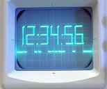
You are proud of your expensive oscilloscope, now you can turn it into a cheap digital clock!
Overview
You are proud of your expensive oscilloscope, now you can turn it into a cheap digital clock! Uses 2-bit R2R DAC for 4 voltage levels. Three frames per digit due to retinal persistence.
How to set up
Oscilloscope setup: timebase 0.1ms, 1V/div, external trigger. RA0 triggers oscilloscope vertical sync.
Circuit Schematic
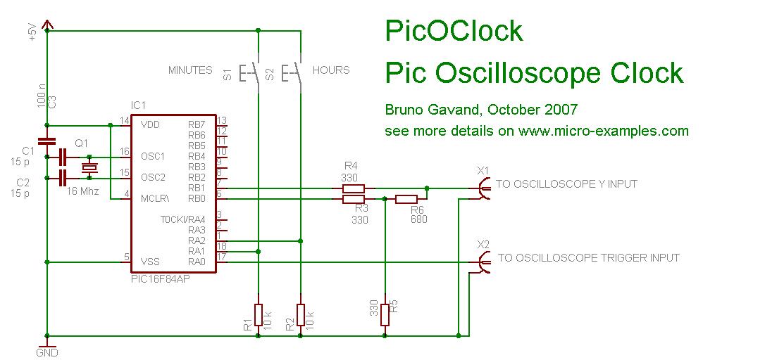
- 2-bit R2R DAC made by resistor ladder R3-R6 (680/330 ohms) driven by RB0/RB1.
- Tested with PIC16F84A and PIC16F877A.
Frame Rendering
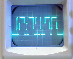
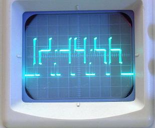
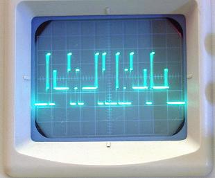
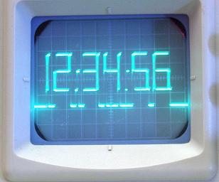
Each digit is rendered across 3 frames (upper, middle, lower horizontal lines) using retinal persistence to display the full character.
C Source Code
picoClock.c
/*
*******************************************************************************
* PICOCLOCK : PIC Oscilloscope CLOCK
*******************************************************************************
*
* This program shows how to display a digital clock on an oscilloscope
* with a PIC and only 4 resistors.
*
* Circuit schematics :
*
* ------------+
* RA0 +----------------> to oscilloscope X trigger input
* |
* RA1 +----------------> pull-up, button to ground : minutes adjustment
* RA2 +----------------> pull-up, button to ground : hours adjustment
* PIC | ____
* RB1 +----|____|-----+----------> to oscilloscope Y input
* | 680 |
* | +-+
* | | | 330
* | +-+
* | ____ |
* RB0 +----|____|-----+
* | 680 |
* ------------+ +-+
* | | 680
* +-+
* |
* -----
* --- GND
* -
*
* Oscilloscope setup :
* set timebase to 0.1 ms, V/div = 1 V
* select external trigger.
*
* source code for mikro C compiler V7.0.0.3
* feel free to use this code at your own risks
*
* target : PIC16 or PIC18, 16 Mhz crystal
* HS clock, no watchdog.
*
* tested with PIC16F84A and PIC16F877A
*
*******************************************************************************
*/
#define TRIGGER PORTA.F0 // oscilloscope trigger output
#define KEY PORTA & 0b110 // input keys mask
#define KEY_MIN_UP PORTA & 0b010 // minute adjust button
#define KEY_HH_UP PORTA & 0b100 // hour adjust button
/*
* 2 bits R2R DAC gives 4 output levels :
*/
#define HIGH PORTB = 0b11 // upper line
#define MID PORTB = 0b10 // middle line
#define LOW PORTB = 0b01 // lower line
#define ZERO PORTB = 0b00 // lowest line
#define MAX_SCALER 15625 // timer 0 overflows/sec @ 16 MHz
#define MAX_DIGIT 6 // number of digits to display
#define SLOTS (MAX_DIGIT * 3 + 4) // time slots: 2 header, 3/digit, 2 trailer
/*
* 10 digits 7 segment encoding + blank
*/
const unsigned char septSeg[11] = { 0x3f, 0x06, 0x5b, 0x4f, 0x66, 0x6d, 0x7d, 0x07, 0x7f, 0x6f, 0x00 } ;
/*
* slot index for digit start
*/
const unsigned char sIdx[] = {1, 4, 8, 11, 15, 18} ;
unsigned char display[MAX_DIGIT] ; // digit to be displayed
/*
* time slot encoded line flags :
* bit 0 is upper line
* bit 1 is middle line
* bit 2 is lower line
* bit 6 is lower vertical bar
* bit 7 is upper vertical bar
*/
unsigned char line[SLOTS] ;
unsigned char dIdx = 0 ; // time slot counter
unsigned char fIdx = 0 ; // frame counter
unsigned int scaler = 0 ; // RTC scaler
unsigned char ss = 0, mn = 0, hh = 0 ; // RTC
void delay10us()
{
Delay_us(10) ;
}
/*
* ISR
*/
void interrupt(void)
{
if(INTCON.T0IF)
{
scaler++ ;
if(scaler > MAX_SCALER)
{
scaler = 0 ;
ss++ ;
if(ss == 60)
{
ss = 0 ;
mn++ ;
if(mn == 60)
{
mn = 0 ;
hh++ ;
if(hh == 24)
{
hh = 0 ;
}
}
}
}
if(line[dIdx].F6 && line[dIdx].F7) // full vertical bar
{
LOW, HIGH, LOW, HIGH ;
LOW, HIGH, LOW, HIGH ;
LOW, HIGH, LOW, HIGH ;
LOW, HIGH, LOW, HIGH ;
LOW, HIGH, LOW, HIGH ;
LOW, HIGH, LOW, HIGH ;
LOW, HIGH, LOW, HIGH ;
LOW, HIGH, LOW, HIGH ;
}
else if(line[dIdx].F6) // lower vertical bar
{
MID, LOW, MID, LOW ;
MID, LOW, MID, LOW ;
MID, LOW, MID, LOW ;
MID, LOW, MID, LOW ;
MID, LOW, MID, LOW ;
MID, LOW, MID, LOW ;
MID, LOW, MID, LOW ;
MID, LOW, MID, LOW ;
}
else if(line[dIdx].F7) // upper vertical bar
{
MID, HIGH, MID, HIGH ;
MID, HIGH, MID, HIGH ;
MID, HIGH, MID, HIGH ;
MID, HIGH, MID, HIGH ;
MID, HIGH, MID, HIGH ;
MID, HIGH, MID, HIGH ;
MID, HIGH, MID, HIGH ;
MID, HIGH, MID, HIGH ;
}
if(dIdx == 7) // hour:minute separator
{
LOW, Delay10us() ;
MID, Delay10us() ;
}
else if(dIdx == 14) // minute:second separator
{
if(scaler < MAX_SCALER / 2) // blink 0.5 Hz
{
LOW, Delay10us() ;
MID, Delay10us() ;
}
}
switch(fIdx)
{
case 0: // upper line
if(line[dIdx] & 1)
{ HIGH ; }
else
{ ZERO ; }
break ;
case 1: // middle line
if(line[dIdx] & 2)
{ MID ; }
else
{ ZERO ; }
break ;
case 2: // lower line
if(line[dIdx] & 4)
{ LOW ; }
else
{ ZERO ; }
break ;
}
dIdx++ ;
if(dIdx == SLOTS)
{
dIdx = 0 ;
TRIGGER = 1 ; // trigger the scope
fIdx++ ;
if(fIdx == 3)
{
fIdx = 0 ;
}
TRIGGER = 0 ;
}
INTCON.T0IF = 0 ;
}
}
/*
* main entry
*/
void main()
{
#ifdef P16F877A
ADCON1 = 7 ;
CMCON = 7 ;
#endif
TRISA = 0b110 ;
PORTA = 0 ;
TRISB = 0 ;
PORTB = 0 ;
memset(&line, 0, sizeof(line)) ;
memset(display, 0, sizeof(display)) ;
OPTION_REG = 0b11011000 ; // timer 0 prescaler 1:1
INTCON = 0b10100000 ; // start interrupts
for(;;)
{
unsigned char i ;
if(KEY) // button pressed?
{
if(KEY_MIN_UP) // adjust minutes
{
ss = 0 ;
mn++ ;
}
else if(KEY_HH_UP) // adjust hours
{
ss = 0 ;
hh++ ;
}
mn %= 60 ;
hh %= 24 ;
Delay_ms(100) ; // debounce
}
/*
* prepare display buffer
*/
display[5] = ss % 10 ; // seconds
display[4] = ss / 10 ;
display[3] = mn % 10 ; // minutes
display[2] = mn / 10 ;
display[1] = hh % 10 ; // hours
display[0] = (hh > 9) ? hh / 10 : 10 ; // blank if zero
/*
* prepare time slot flags
*/
for(i = 0 ; i < MAX_DIGIT ; i++)
{
unsigned char s ;
unsigned char *p ;
s = septSeg[display[i]] ; // 7 segment encoding
p = &line[sIdx[i]] ; // pointer to time slot
(*p).F0 = s.F0 ; // a segment
(*p).F1 = s.F6 ; // g segment
(*p).F2 = s.F3 ; // d segment
(*p).F6 = s.F4 ; // e segment
(*p).F7 = s.F5 ; // f segment
p++ ; // center part
(*p).F0 = s.F0 ; // a (continuation)
(*p).F1 = s.F6 ; // g (continuation)
(*p).F2 = s.F3 ; // d (continuation)
p++ ; // right part
(*p).F6 = s.F2 ; // b segment
(*p).F7 = s.F1 ; // c segment
}
}
}