Views
Views
From www.micro-examples.com
(Difference between revisions)
(→PicoOClock : Turn your oscilloscope into a digital clock) |
(→PicoOClock : Turn your oscilloscope into a digital clock) |
||
| Line 5: | Line 5: | ||
{{#ev:youtube|MJ79od3IYmM}} | {{#ev:youtube|MJ79od3IYmM}} | ||
| − | + | [[File:PicOClock-frame1.jpg]] | |
| − | File:PicOClock-frame1.jpg | + | [[File:PicOClock-frame2.jpg]] |
| − | File:PicOClock-frame2.jpg | + | [[File:PicOClock-frame3.jpg]] |
| − | File:PicOClock-frame3.jpg | + | [[File:PicOClock-frame4.jpg]] |
| − | File:PicOClock-frame4.jpg | + | |
| − | + | ||
If you like it, please see also my [[Pic Pal Video Library]], and also [[PicoOSD]] | If you like it, please see also my [[Pic Pal Video Library]], and also [[PicoOSD]] | ||
Revision as of 22:06, 9 February 2012
An On-Screen-Display with only 5 components !
Contents |
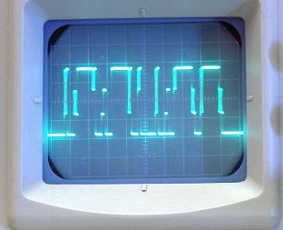
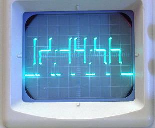
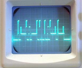
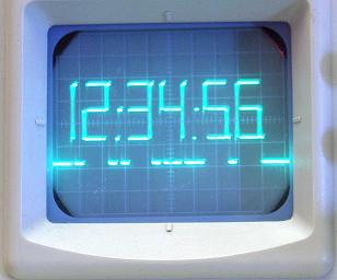
PicoOClock : Turn your oscilloscope into a digital clock
Let me introduce PicoOClock to you with this short video clip :
If you like it, please see also my Pic Pal Video Library, and also PicoOSD
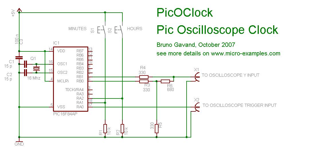
Circuit Schematic
C Source code
/*
*******************************************************************************
* PICOCLOCK : PIC Oscilloscope CLOCK
*******************************************************************************
*
* This program shows how to display a digital clock on an oscilloscope
* with a PIC and only 4 resistors.
*
* Circuit schematics :
*
* ------------+
* RA0 +----------------> to oscilloscope X trigger input
* |
* RA1 +----------------> pull-up, button to ground : minutes adjustment
* RA2 +----------------> pull-up, button to ground : hours adjustment
* PIC | ____
* RB1 +----|____|-----+---------> to oscilloscope Y input
* | 680 |
* | +-+
* | | | 330
* | +-+
* | ____ |
* RB0 +----|____|-----+
* | 680 |
* ------------+ +-+
* | | 680
* +-+
* |
* -----
* --- GND
* -
*
* Oscilloscope setup :
* set timebase to 0.1 ms, V/div = 1 V
* select external trigger.
*
* source code for mikro C compiler V7.0.0.3
* feel free to use this code at your own risks
* and don't bother me if you get addicted watching this clock.
*
* target : PIC16 or PIC18, 16 Mhz crystal
* HS clock, no watchdog.
*
* tested with PIC16F84A and PIC16F877A
*
* Author : Bruno Gavand, October 2007
* see more details on http://www.micro-examples.com/
*
*******************************************************************************
*/
#define TRIGGER PORTA.F0 // this output is to be connected to oscilloscope trigger input
#define KEY PORTA & 0b110 // input keys mask
#define KEY_MIN_UP PORTA & 0b010 // minute adjust button
#define KEY_HH_UP PORTA & 0b100 // hour adjust button
/*
* 2 bits R2R DAC gives 4 output levels :
*/
#define HIGH PORTB = 0b11 // uper line
#define MID PORTB = 0b10 // middle line
#define LOW PORTB = 0b01 // lower line
#define ZERO PORTB = 0b00 // lowest line
#define MAX_SCALER 15625 // number of timer 0 overflow per second @ 16 Mhz = 16000000 / 4 / 256
#define MAX_DIGIT 6 // number of digits to be displayed
#define SLOTS (MAX_DIGIT * 3 + 4) // number of time slots : 2 for header, 3 per digits, 2 for trailer
/*
* 10 digits 7 segment encoding + blank
*/
const unsigned char septSeg[11] = { 0x3f, 0x06, 0x5b, 0x4f, 0x66, 0x6d, 0x7d, 0x07, 0x7f, 0x6f, 0x00 } ;
/*
* slot index for digit start
*/
const unsigned char sIdx[] = {1, 4, 8, 11, 15, 18} ;
unsigned char display[MAX_DIGIT] ; // digit to be displayed
/*
* time slot encoded line flags :
* bit 0 is upper line
* bit 1 is middle line
* bit 2 is lower line
* (if no line flag is set, spot is redirected to lowest line)
* bit 6 is lower vertical bar
* bit 7 is upper vertical bar
*/
unsigned char line[SLOTS] ;
unsigned char dIdx = 0 ; // time slot counter
unsigned char fIdx = 0 ; // frame counter
unsigned int scaler = 0 ; // RTC scaler
unsigned char ss = 0, mn = 0, hh = 0 ; // RTC
/*
* around 10 micro-second delay
*/
void delay10us()
{
Delay_us(10) ;
}
/*
* ISR
*/
void interrupt(void)
{
if(INTCON.T0IF) // if timer 0 overflow
{
scaler++ ; // increment scaler
if(scaler > MAX_SCALER) // one second has expired ?
{
scaler = 0 ; // clear scaler
ss++ ; // next second
if(ss == 60) // last second in minute ?
{
ss = 0 ; // clear second
mn++ ; // next minute
if(mn == 60) // last minute in hour ?
{
mn = 0 ; // clear minute
hh++ ; // next hour
if(hh == 24) // last hour in day ?
{
hh = 0 ; // clear hour
}
}
}
}
if(line[dIdx].F6 && line[dIdx].F7) // if full vertical bar
{
LOW, HIGH, LOW, HIGH ;
LOW, HIGH, LOW, HIGH ;
LOW, HIGH, LOW, HIGH ;
LOW, HIGH, LOW, HIGH ;
LOW, HIGH, LOW, HIGH ;
LOW, HIGH, LOW, HIGH ;
LOW, HIGH, LOW, HIGH ;
LOW, HIGH, LOW, HIGH ;
}
else if(line[dIdx].F6) // if lower vertical bar
{
MID, LOW, MID, LOW ;
MID, LOW, MID, LOW ;
MID, LOW, MID, LOW ;
MID, LOW, MID, LOW ;
MID, LOW, MID, LOW ;
MID, LOW, MID, LOW ;
MID, LOW, MID, LOW ;
MID, LOW, MID, LOW ;
}
else if(line[dIdx].F7) // if upper vertical bar
{
MID, HIGH, MID, HIGH ;
MID, HIGH, MID, HIGH ;
MID, HIGH, MID, HIGH ;
MID, HIGH, MID, HIGH ;
MID, HIGH, MID, HIGH ;
MID, HIGH, MID, HIGH ;
MID, HIGH, MID, HIGH ;
MID, HIGH, MID, HIGH ;
}
if(dIdx == 7) // hour : minute separator
{
LOW, Delay10us() ;
MID, Delay10us() ;
}
else if(dIdx == 14) // minute : second separator
{
if(scaler < MAX_SCALER / 2) // blink 0.5 Hz
{
LOW, Delay10us() ;
MID, Delay10us() ;
}
}
switch(fIdx) // depending on frame index
{
case 0: // upper line
if(line[dIdx] & 1)
{
HIGH ;
}
else
{
ZERO ;
}
break ;
case 1: // middle line
if(line[dIdx] & 2)
{
MID ;
}
else
{
ZERO ;
}
break ;
case 2: // lower line
if(line[dIdx] & 4)
{
LOW ;
}
else
{
ZERO ;
}
break ;
}
dIdx++ ; // next slot
if(dIdx == SLOTS) // last slot ?
{
dIdx = 0 ; // clear slot
TRIGGER = 1 ; // triggers the scope
fIdx++ ; // next frame
if(fIdx == 3) // last frame ?
{
fIdx = 0 ; // clear frame
}
TRIGGER = 0 ; // end trigger
}
INTCON.T0IF = 0 ; // clear timer 0 overflow
}
}
/*
* main entry
*/
void main()
{
#ifdef P16F877A
/*
* set PORTA as digital I/O
*/
ADCON1 = 7 ;
CMCON = 7 ;
#endif
TRISA = 0b110 ; // PORTA direction register
PORTA = 0 ;
TRISB = 0 ; // PORTB is output
PORTB = 0 ;
/*
* clear buffers
*/
memset(&line, 0, sizeof(line)) ;
memset(display, 0, sizeof(display)) ;
OPTION_REG = 0b11011000 ; // timer 0 prescaler is 1:1
INTCON = 0b10100000 ; // start interrupts
for(;;) // main loop
{
unsigned char i ;
if(KEY) // is a button pressed ?
{
if(KEY_MIN_UP) // adjust minutes
{
ss = 0 ;
mn++ ;
}
else if(KEY_HH_UP) // adjust hours
{
ss = 0 ;
hh++ ;
}
mn %= 60 ; // prevent minute overflow
hh %= 24 ; // prevent hours overflow
Delay_ms(100) ; // debounce
}
/*
* prepare display buffer
*/
display[5] = ss % 10 ; // seconds
display[4] = ss / 10 ;
display[3] = mn % 10 ; // minutes
display[2] = mn / 10 ;
display[1] = hh % 10 ; // hours
display[0] = (hh > 9) ? hh / 10 : 10 ; // blank first digit if zero
/*
* prepare time slot flags
*/
for(i = 0 ; i < MAX_DIGIT ; i++) // for each digit
{
unsigned char s ;
unsigned char *p ;
s = septSeg[display[i]] ; // get 7 segment encoding
p = &line[sIdx[i]] ; // get pointer to time slot, left part of the digit
(*p).F0 = s.F0 ; // a segment
(*p).F1 = s.F6 ; // g segment
(*p).F2 = s.F3 ; // d segment
(*p).F6 = s.F4 ; // e segment
(*p).F7 = s.F5 ; // f segment
p++ ; // next slot, center part of the digit
(*p).F0 = s.F0 ; // a segment (continuation)
(*p).F1 = s.F6 ; // g segment (continuation)
(*p).F2 = s.F3 ; // d segment (continuation)
p++ ; // next slot, right part of the digit
(*p).F6 = s.F2 ; // b segment
(*p).F7 = s.F1 ; // c segment
}
}
}
Download project
Download PicoOSD-project.zip file for mikroC : File:PicoOSD-project.zip
Includes :
- mikroC PRO project files for PIC12F683, should work also with most of PIC
- picoOSD C source code
- picoOSD .HEX files
Discussion and comments
You need JavaScript enabled for viewing comments
| powered by commenterra | Recent comments |
