Views
Views
(→Circuit Schematic) |
(→Circuit Schematic) |
||
| Line 9: | Line 9: | ||
==Circuit Schematic== | ==Circuit Schematic== | ||
| − | This project is designed to run on an EasyPIC3 development board, so no circuit schematic is available. | + | This project is designed to run on an [[EasyPIC3]] development board, so no circuit schematic is available. |
This is how to connect the 4-wires resistive touchpanel directly to the PIC : | This is how to connect the 4-wires resistive touchpanel directly to the PIC : | ||
Revision as of 13:06, 9 February 2012
Design your own GLCD Touch Clock
Contents |
TouchClock : a PIC18 GLCD touchscreen clock
Let me introduce TouchClock to you with this short video clip :
The idea of this project is to use a graphic LCD with a touchscreen and a built-in sprite editor to design your own clock, and shows how to connect a resistive touchscreen directly to a PIC with no additional hardware.
This project also includes a ready-to use touchscreen library for PIC
Circuit Schematic
This project is designed to run on an EasyPIC3 development board, so no circuit schematic is available.
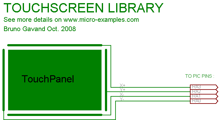
This is how to connect the 4-wires resistive touchpanel directly to the PIC :
How the library reads the X raw coordinate of a touch :
- X+ and X- are in high Z : RA0 and RA2 are inputs
- Y+ is set to +5V : RA3 is output high
- Y- is set to 0V : RA1 is output low
- X+ voltage is read by ADC
- Y+ is set to 0V : RA3 is output low
- Y- is set to 5V: RA1 is output high
- X- voltage is read by ADC and averaged with X+ value, the result is the raw X coordinate.
- The same is then done to read the Y coordinate, please see TSlib.c file in .ZIP file below.
X and Y raw coordinates are then adjusted using calibration coordinates to get X and Y coordinates in pixel.
C Source code
Since this project has multiple source files, source code is not expanded here : please download archive file below.
Download project
Download TouchClock-project.zip file for mikroC : File:TouchClock-project.zip
Includes :
- mikroC PRO project files for PIC18F4620, should work also with most PICs
- TouchClock C source code with resistive touchscreen library
- TouchClock .HEX files
Discussion and Comments
| powered by commenterra | Recent comments |
