A PIC16F84A-based LED clock with DCF-77 atomic time synchronization.
Overview
This project uses a PIC16F84A with a 4x7 segment LED display. It supports hours/minutes or minutes/seconds display modes. The DCF77 atomic clock provides automatic time set-up. The firmware uses only 861 bytes of ROM and 62 bytes of RAM.
What is DCF77?
DCF77 is a German radio station broadcasting on 77.5 KHz, transmitting atomic clock time from Frankfurt. The signal encodes time in a 59-bit frame: a 100ms pulse represents a 0 bit, a 200ms pulse represents a 1 bit. One pulse is sent per second, with a 2-second gap marking the minute synchronization point. The signal range is approximately 2000 km.
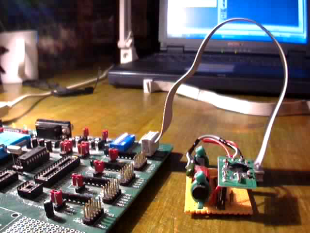
Building a DCF77 Receiver
Ready-made DCF77 receiver modules are available for 12-18 euros. They have 3 pins: Gnd, Pulse, and Vcc. The firmware handles both positive and negative logic modules. The ferrite antenna must be oriented perpendicular to the direction of Frankfurt for best reception.
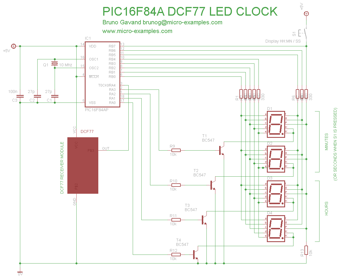
Circuit Schematic
How to Use
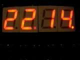
When not locked to the DCF77 signal, the display shows the current frame bit number and pulse signal indicator. Once locked, the display shows hours:minutes. Pressing RB7 toggles to minutes:seconds display mode.
C Source Code
/*
 * DCF-77 LED CLOCK
 *
 * PIC16F84A
 * 10 Mhz crystal, HS clock
 *
 * PORTA.0->3, out : 7 segment cathode control
 * PORTA.4, in : DCF pulse input
 *
 * PORTB.0->7, out : 7 segment output
 * PORTB.7, in : button input
 *
 *******************************************************************************
 */

#define MAXCOUNT        9766    // TMR0 overflows in 1 second
#define ADJUST          96      // extra ticks in 1 second

#define timer_d_min 14000       // TMR0 overflows in ~2 seconds
#define timer_h_0 640           // TMR0 overflows in ~0.1 second
#define timer_h_1 1400          // TMR0 overflows in ~0.2 second

unsigned int    tmrh ;          // TMR0 overflows since pulse high
unsigned int    tmrd ;          // TMR0 overflows since pulse down
unsigned char   bitnum = 0 ;    // last valid bit received
char            last_bit ;      // value of last valid bit
unsigned char   parity ;        // positive bits count
unsigned char   full = 0 ;      // DCF frame complete
unsigned char   locked = 0 ;    // clock adjusted
unsigned char   mode = 1 ;      // 0:positive, 1:negative logic
unsigned char   mn ;            // next minutes in DCF frame
unsigned char   hh ;            // next hours in DCF frame
unsigned int    scaler ;        // TMR0 overflows for RTC
unsigned char   rhh = 12, rmn = 34, rss = 56 ; // RTC hours, minutes, seconds
unsigned char   digiled[4] ;    // 7 segment for each display
unsigned char   septSeg[10] = { 0x3f, 0x06, 0x5b, 0x4f, 0x66, 0x6d, 0x7c, 0x07, 0x7f, 0x67 } ;
unsigned char   digit ;         // current digit in mux sequence
unsigned char   kp ;            // button state
unsigned char   dp = 0 ;        // decimal points
unsigned char   i ;

/*
 * ISR: called on each TMR0 overflow
 */
void    interrupt(void)
        {
        /* test DCF pulse, invert if negative logic */
        if(PORTA.F4 ^ mode)                             // pulse high?
                {
                tmrh++ ;
                if(tmrd > timer_d_min)                  // pause > 2 sec?
                        {
                        bitnum = 0 ;
                        if(full)                        // frame complete?
                                {
                                rhh = hh ;              // set RTC
                                rmn = mn ;
                                rss = 0 ;
                                scaler = 0 ;
                                locked = 1 ;
                                }
                        mn = hh = 0 ;
                        parity = 0 ;
                        full = 0 ;
                        dp.F3 = 1 ;
                        }
                tmrd = 0 ;
                }
        else
                {
                tmrd++ ;
                if(tmrh > 0)
                        {
                        if(tmrh > timer_h_1)           // bit = 1
                                {
                                last_bit = 1 ;
                                switch(bitnum)
                                        {
                                        case 21: mn++ ; break ;
                                        case 22: mn += 2 ; break ;
                                        case 23: mn += 4 ; break ;
                                        case 24: mn += 8 ; break ;
                                        case 25: mn += 10 ; break ;
                                        case 26: mn += 20 ; break ;
                                        case 27: mn += 40 ; break ;
                                        case 29: hh++ ; break ;
                                        case 30: hh += 2 ; break ;
                                        case 31: hh += 4 ; break ;
                                        case 32: hh += 8 ; break ;
                                        case 33: hh += 10 ; break ;
                                        case 34: hh += 20 ; break ;
                                        }
                                if((bitnum != 28) && (bitnum != 35) && (bitnum != 58))
                                        { parity++ ; }
                                bitnum++ ;
                                }
                        else if(tmrh > timer_h_0)       // bit = 0
                                {
                                if(bitnum == 20)        // start bit should be 1
                                        {
                                        last_bit = -1 ;
                                        bitnum = 0 ;
                                        dp.F3 = 0 ;
                                        }
                                else
                                        {
                                        last_bit = 0 ;
                                        bitnum++ ;
                                        }
                                }
                        else
                                {
                                last_bit = -1 ;         // garbage
                                bitnum = 0 ;
                                dp.F3 = 0 ;
                                }

                        if(bitnum == 21) { parity = 0 ; }

                        /* parity check */
                        if((bitnum == 29) || (bitnum == 36) || (bitnum == 59))
                                {
                                if((parity & 1) != last_bit)
                                        {
                                        bitnum = 0 ;
                                        dp.F3 = 0 ;
                                        }
                                parity = 0 ;
                                }

                        if(bitnum == 59) { full++ ; }
                        }
                tmrh = 0 ;
                }

        /* real time clock */
        scaler++ ;
        if(scaler == MAXCOUNT)
                {
                TMR0 += ADJUST ;
                scaler = 0 ;
                rss++ ;
                if(rss == 60)
                        {
                        rss = 0 ;
                        rmn++ ;
                        if(rmn == 60)
                                {
                                rmn = 0 ;
                                rhh++ ;
                                if(rhh == 24) { rhh = 0 ; }
                                }
                        }
                }

        dp.F1 = PORTA.F4 ^ mode ;       // pulse level on decimal point
        INTCON.T0IF = 0 ;
        }

/*
 * program entry
 */
main()
        {
        TRISA = 0b00010000 ;
        TRISB = 0x00 ;

        INTCON = 0b10100000 ;           // T0IF and GIE enabled
        OPTION_REG = 0b11011000 ;       // no prescaler

        for(;;)
                {
                if(locked > 0)                  // RTC up to date?
                        {
                        if(kp)                          // key pressed?
                                {
                                /* display MN:SS */
                                digiled[0] = septSeg[rmn / 10] ;
                                digiled[1] = septSeg[rmn % 10] ;
                                digiled[2] = septSeg[rss / 10] ;
                                digiled[3] = septSeg[rss % 10] ;
                                }
                        else
                                {
                                /* display HH:MN */
                                digiled[0] = (rhh < 10) ? 0 : septSeg[rhh / 10] ;
                                digiled[1] = septSeg[rhh % 10] ;
                                digiled[2] = septSeg[rmn / 10] ;
                                digiled[3] = septSeg[rmn % 10] ;
                                }
                        }
                else
                        {
                        /* not locked: show DCF frame info */
                        digiled[0] = 0 ;
                        digiled[1] = 0 ;
                        digiled[2] = septSeg[bitnum / 10] ;
                        digiled[3] = septSeg[bitnum % 10] ;
                        }

                /* set decimal points */
                digiled[0].F7 = dp.F0 ;
                digiled[1].F7 = dp.F1 ;
                digiled[2].F7 = dp.F2 ;
                digiled[3].F7 = dp.F3 ;

                PORTA = 0 ;
                PORTB = 0 ;

                TRISB = 0x80 ;                  // RB7 as input
                kp = PORTB.F7 ;                 // read key
                TRISB = 0x00 ;

                digit++ ;
                if(digit > 3)
                        {
                        digit = 0 ;
                        i = 0x01 ;
                        }
                else
                        {
                        i = 0x01 << digit ;
                        }

                PORTB = digiled[digit] ;
                PORTA = i ;
                }
        }
Download
DCF-77 LED Clock project files
Download the source code and pre-compiled HEX file:
- dcf77clock.c — mikroC source code
- dcf77clock.hex — pre-compiled HEX for PIC16F84A (10 MHz crystal)